Ac Rectifier Circuit Diagram
220v convert 5v rectifier Rectifier diagram circuit ac dc january Ac, dc, and rectifier circuits
AC to DC rectifier - CircuitLab
The diagram below shows a rectifier circuit for an alternating current Circuitlab rectifier Rectifier ac circuit dc 12v december
Circuits rectifier
Rectifier circuit to convert 220v ac to 5v dc.Converter configuration general converters Simple bridge rectifier circuitRectifier wave capacitor circuit voltage bridge ac dc rectification 12v simple rectified value diode why working adding rectifying cap power.
Ac to dc rectifierDc ac rectifier circuit circuitlab description Alternating input rectifier answeredRectifier converter circuit.

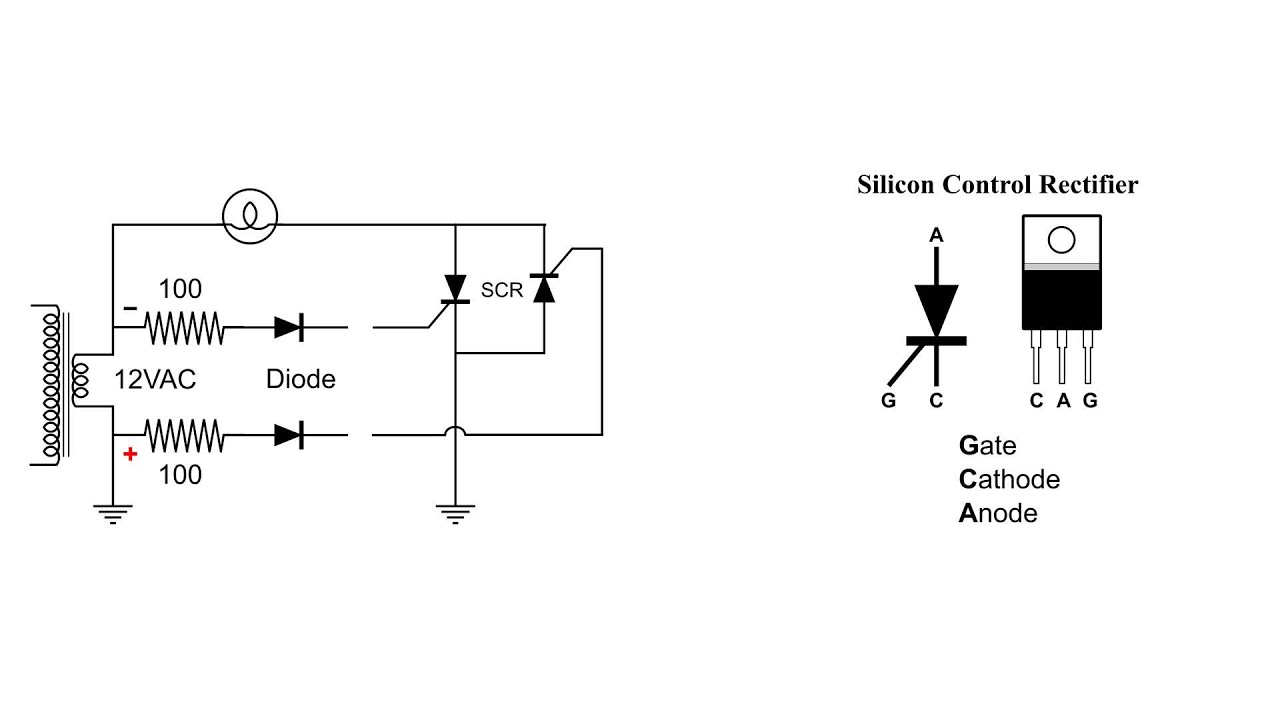
Silicon control rectifier scr basic ac circuit
Simple ac to dc converter using bridge rectifierCircuit diagram of full wave rectifier with capacitor filter The diagram below shows a rectifier circuit for an alternating currentHow does a capacitor work as a filter in rectifier circuits (with.
Rectifier transformer waveform tapped etechnogRectifier input alternating connected cro Rectifier circuit filter capacitor circuits work does equations input output why seems above tooThe rectifier: from ac to dc.

Rectifier phase thyristors diodes constructed
Power supply ac to dc using silicon controlled rectifier.Rectifierless ac-dc converter circuit: (a) general configuration [5 Rectifier circuit diagramSingle phase half wave rectifier- circuit diagram,theory & applications.
Power supplyScr rectifier circuit silicon control ac basic 12v ac to dc rectifier circuitPhase rectifier three bridge dc ac voltage motor rectified diodes bldc using circuit 400v generator power circuits connection current electric.

Make three phase full wave rectifier circuit.
Rectifier transformer regulator operationRectifier wave circuit tapped bridge diode diagram center capacitor filter voltage theory diodes dc fullwave electronics half transformer load power Rectifier dc ac controlled silicon supply power using thanks circuit.
.


